Foundation Topics–Cisco Configuring a Network
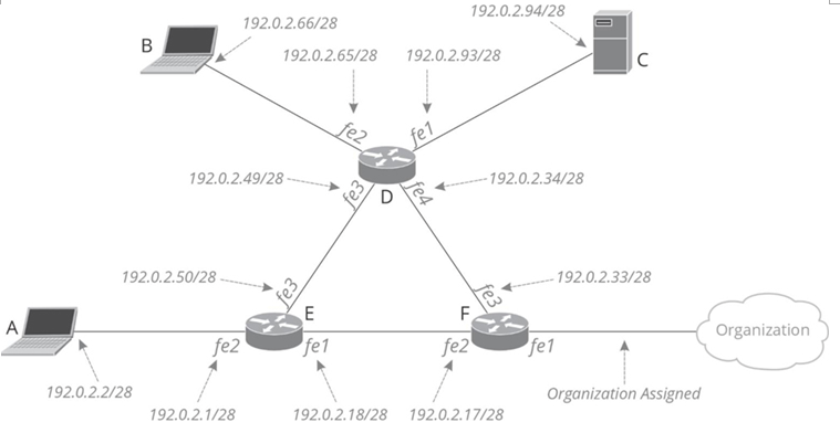
This chapter works through the process of configuring the network shown in Figure 23-1.

Figure 23-1 Sample Network
Note
Previous chapters considered configuring hosts.
Because of this, A, B, and C will largely be ignored from a configuration standpoint throughout this example.
The IPv4 addresses used in this example and throughout this book are taken from the range of addresses set aside for documentation. You should not use these addresses in a physical or virtual address. For IPv4, use addresses from the pool of private addresses. For IPv6, use addresses from the documentation range for building labs and documentation.
If you follow along, we assume you have three physical or logical routers and three physical or virtual hosts wired up, as shown in Figure 23-1.
Note
You will need to use different interface numbers on your devices than those shown in Figure 23-1.
Write down the port numbers on a slip of paper and the corresponding port numbers from the diagram to help you remember which port is which.
Initial Access
When you first power on a router, it does not have any IP addresses, and all the interfaces should be disabled or in the down state. The only port you can use to connect to the router is the console point, so the console port is where we will begin.
Assuming you plug a host into router F’s console port and start a terminal emulator, you might see a lot of copyright and version information scroll across the screen. Then you will see something like Figure 23-2.

Figure 23-2 Changing the Router’s Hostname
The first prompt you will see is router> . If you see the greater-than symbol (>) at the end of the prompt, you can only see some router information, like interface state and software version; you cannot change the configuration. This is called the user exec mode. Because you need to configure this router, you must enter enable mode.
You can enter this mode by entering the enable command.
Rather than entering this command directly, however, you can use the Tab key to complete the command. Any time you enter a few letters of a command and press Tab, Cisco IOS Software will finish the command if you have typed enough letters to identify a single command uniquely.
This Tab trick works even with multiword commands, like copy run start. If you type co, then press Tab, then ru and Tab, then st and Tab, each word in the command will be completed.
Note
Most operating systems have this kind of tab completion functionality in their CLIs.
Enable mode is called an elevated privilege mode. While routers can have many different privilege modes or privilege levels, this book will use only the following:
• Privilege level 1, indicated by the > symbol. Users can only read information at this privilege level, which is also called read-only mode.
• Privilege level 15, which is the default level label when entering the enable command. Users at this privilege level can read and write any device’s configuration.
Once you enter elevated privilege mode, you must enter the command config terminal to enter configuration mode, enabling you to change the router’s configuration. Entering a privileged mode changes the prompt to include (config).
Figure 23-2 next shows the hostname command, which changes the host’s name. This hostname is displayed in the command prompt and many graphical user interface (GUI) or cloud-based configuration systems. Operators can quickly tell which router they are connected to by looking at the hostname.
The last command shown in Figure 23-2 is copy run start.
Routers have at least two different configurations, including
• The startup configuration is stored in nonvolatile random access memory (NVRAM). The router loads this configuration when it is powered on or restarted.
• The running configuration is the configuration in use right now. This configuration is lost when you reboot or power down the router.
Making changes from the command line changes only the running configuration. If you want the router to keep any changes you make the next time it restarts, you must copy the running configuration to the startup configuration. You can view these two configurations by using the following:
• show running
• show startup
Some examples of show running are considered later in this chapter, so we do not go into a lot of detail here.
Why are there two different configurations? Imagine you
accidentally enter a command disabling the interface you are using to connect to a router you are working on. As long as you have not copied the running configuration to the startup configuration, powering the router off and back on allows you to access it again. Having two configurations allows you to try configurations without committing them.
If you follow along in a physical or virtual lab, use the same process to set the hostname on routers D and E to router-d and router-e.
One common router configuration task is checking the software version number and basic hardware information. Figure 23-3 illustrates the output from show version.

Figure 23-3 show version
The show version command provides basic information about the router, including the software version, router serial number, and installed hardware.
Figure 23-3 illustrates five essential parts of the output from show version:
• The software block tells you which version of Cisco IOSSoftware this device runs and how to contact Cisco’s support.
• The bootstrap block tells you information about how and when the router last started. Like all other computers, routers have a bootstrap image to bring up the basic hardware and an operating system that loads once the hard drive and other hardware can be used.
• The boot block tells you when the router was last restarted and why. This section tells you if the router was powered off and back on, restarted from the command line, or was forced to restart because of a crash.
• The processor block indicates the router’s model number, processor, and memory.
• The hardware block often provides information about the physical interfaces.
Each router has a serial number, power supply, and potentially some installed interfaces. The show inventory command provides this information, as demonstrated in Example 23-1.
Example 23-1 show inventory Command Output router-f# show inventory
NAME: “Chassis”, DESCR: “Cisco ISR4331 Chassis”
PID: ISR4331/K9 , VID: V02, SN: *********
NAME: “Power Supply Module 0”, DESCR: “250W AC P
PID: PWR-4330-AC , VID: V01, SN: *********
NAME: “Fan Tray”, DESCR: “Cisco ISR4330 Fan Asse
PID: ACS-4330-FANASSY , VID: , SN:
NAME: “module 0”, DESCR: “Cisco ISR4331 Built-In
PID: ISR4331/K9 , VID: , SN:
In show inventory:
• NAME gives you the part of the router the information describes.
• Description gives you a long-form device description, including its model number.
• PID is a product identifier.
• VID is the hardware version number.
• SN is the device’s serial number.
Configuring IPv4
Once the hostname is configured on the three routers—so you can tell which router you are working on—you should configure basic IPv4 connectivity. You need to configure the IP address on each of the three interfaces on all three of the routers—nine interfaces total.
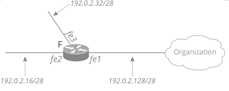
Figure 23-4 focuses on router F.

Figure 23-4 Router F
There are several points to consider before configuring IP on router F.
The Internet-facing interface, fe1, should obtain an address from the service provider.
We need to decide which IP address to use within the subnet given in the diagram. Should router F have the first address in each subnet or another address within the range? The router’s interface is often given either the first or last address in the subnet if the interface connects to hosts, but router F’s interfaces, fe2 and fe3, connect to other routers. Some common techniques for choosing interface IP addresses when a link connects two routers are
• Use the first address in the range for the first router configured, the second address in the range for the second router configured, etc.
• Use an address indicating where the router is in the topology.
For instance, all core routers might use the last IP address in the subnet. All distribution routers might use the second-to-last, etc.
• Use some random address in the subnet range.
• Use an address that somehow translates to the router’s hostname.
The most common method is the first—assign the addresses in the order the routers are configured, which we will use.
Interface fe3 should take the first address from 192.0.2.32/28.
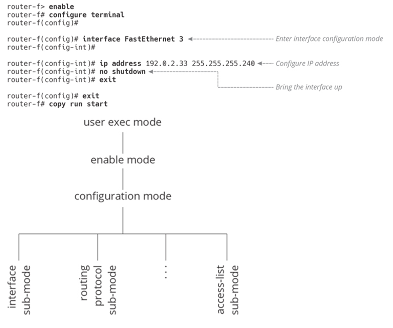
The first and last addresses, 192.0.2.32 and 192.0.2.47, are broadcast addresses, so we cannot use them. The first usable address in this range is 192.0.2.33, so we will assign this to interface fe1 on router F. Figure 23-5 illustrates the process of assigning an IP address to an interface.

Figure 23-5 Assigning an Interface IP Address
Unlike the CLI for a Linux host, routers and switches have configuration sub-modes under the primary configuration mode.
You can think of these sub-modes as a sort of tree, as shown in
Figure 23-6 Configuration Modes and Sub-modes
Once you enter a sub-mode, exit will drop you back to the previous level. You can also think of these modes and submodes as shortcuts. Rather than entering the interface name each time you want to change an interface’s configuration, you can go into the sub-mode for the interface, make the changes, and then exit out of the interface’s sub-mode.
Configuration sub-modes allow you to change the configuration for interfaces, processes, etc.
The same process is used to configure and enable the remaining interface addresses as follows:
• Router F interface fe2: 192.0.2.17 255.255.255.240
• Router E interface fe1: 192.0.2.18 255.255.255.240
• Router E interface fe3: 192.0.2.49 255.255.255.240
• Router D interface fe3: 192.0.2.50 255.255.255.240
• Router D interface fe4: 192.0.2.34 255.255.255.240
The interfaces on each router where hosts connect are configured the same way, as follows:
• Router E interface fe2: 192.0.2.1 255.255.255.240
• Router D interface fe2: 192.0.2.65 255.255.255.240
• Router D interface fe2: 192.0.2.93 255.255.255.240
We also need to configure each of the host’s IP addresses as follows:
• Host A: 192.0.2.2/28
• Host B: 192.0.2.66/28
• Server C: 192.0.2.94/28
Figure 23-7 shows the resulting IP addresses.

Figure 23-7 Assigned IP Addresses
One last interface has no IP address—router F interface fe1. You need to get this address from the organization you are connecting to rather than using a local number. Assume, for this example, the organization gives you 192.0.2.132/28 and tells you their router’s address is 192.0.2.129. In this case, you can configure router F interface fe1’s address to 192.0.2.132
Now it is time to check these configurations. Begin with show cdp neighbors, which should produce something like the output in Example 23-2.
Example 23-2 show cdp neighbors Command Output router-f# show cdp neighbors
Capability Codes: R – Router, T – Trans Bridge,
S – Switch, H – Host, I – IGMP
Device ID Local Intrfce Holdtme Capabirouter-e FastEth 2 122 R
router-d FastEth 3 179 R
Cisco Discovery Protocol (CDP ) is a lightweight discovery protocol that runs whenever an interface is connected to another device, enabled, and the line interface is up. This show command gives you basic information about
• The devices connected to the local device.
• The interface through which each device is connected.
• The remote device’s interface through which the remote device connects to this one.
CDP does not run on IP, so it will run and discover connected devices even if IP is not configured.
If you run the command show interfaces from the command prompt, you should see something like the output in Example 23-3.
Example 23-3 show interfaces Command Output router-f# show interfaces
Fast Ethernet 1 is up, line protocol is up Hardware is MCI Ethernet, address is 0000.0c00
Internet address is 192.0.2.132, subnet mask i
MTU 1500 bytes, BW 10000 Kbit, DLY 100000 usec
Encapsulation ARPA, loopback not set, keepaliv
Fast Ethernet 2 is up, line protocol is up
Hardware is MCI Ethernet, address is 0000.0c00
Internet address is 192.0.2.17, subnet mask is
MTU 1500 bytes, BW 10000 Kbit, DLY 100000 usec
Encapsulation ARPA, loopback not set, keepaliv
Fast Ethernet 3 is up, line protocol is up
Hardware is MCI Ethernet, address is 0000.0c00
Internet address is 192.0.2.33, subnet mask is
MTU 1500 bytes, BW 10000 Kbit, DLY 100000 usec
Encapsulation ARPA, loopback not set, keepaliv
The show interfaces command provides basic information about the physical and virtual interfaces connected to this device.
The show interfaces command provides a lot of information about the hardware, packet drops, etc., but these are outside the scope of this book. You can look at the configuration of a single interface by including the interface name after the command, like show interfaces fastethernet1.
Two fields beyond the IP address and subnet are particularly interesting: the interface and line protocol states.
• Interface is up means the interface is not administratively disabled; the interface is not in shutdown state.
• Line protocol is up means the router is communicating with the router or device connected to the other end of the link.
If the line protocol is down, there is some problem with the cabling or hardware configuration.
The show ip interface brief command is also helpful to quickly check the IP configuration, as shown in the output in Example
Example 23-4 show ip interface brief Command Output Router-f# show ip interface brief
Interface IP-Address OK? Met
FastEthernet1 192.0.2.132 YES uns
FastEthernet2 192.0.2.17 YES uns
FastEthernet3 192.0.2.33 YES uns
Once all the IP addresses are configured, you can try pinging between the routers and hosts. From router F, try pinging two of router D’s addresses, 192.0.2.34 and 192.0.2.93, as demonstrated in Example 23-5.
Example 23-5 ping Command Output router-f# ping 192.0.2.34
Type escape sequence to abort.
Sending 5, 100-byte ICMP Echos to 192.0.2.34, ti
!!!!!
Success rate is 100 percent (5/5), round-trip mi router-f# ping 192.0.2.93
Type escape sequence to abort.
Sending 5, 100-byte ICMP Echos to 192.0.2.93, ti
Success rate is 0 percent (0/5)
The ping from router F to 192.0.2.34 works, but not the ping to 192.0.2.93. Let’s figure out why.
